New
technologies
introduced
Realization of on-site supervision from the viewpoint of the craftsman and labor saving of finished shape management
Revolution in PC bridge construction by linking BIM with AR and surveying
(Consortium led by IHI Construction Service Co., Ltd.)
By Ryota Ieiri, construction IT journalist official website:http://ieiri-lab.jp/
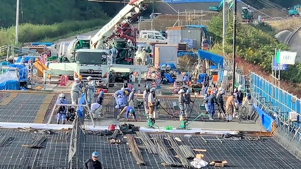
Reinforcing bars are arranged to suit the BIM model for reinforcing bar arrangement
“Move the reinforcing bar forward a bit. OK, stop right there---” At the construction site of the Koryo-Taki PC Bridge superstructure (the project owner: Chugoku Regional Development Bureau, MLIT) in Izumo City, Shimane Prefecture, craftsmen wearing equipment similar to large sunglasses was giving commands for positioning reinforcing bars. Mysteriously, no one at the site was using a measuring tape or the like.
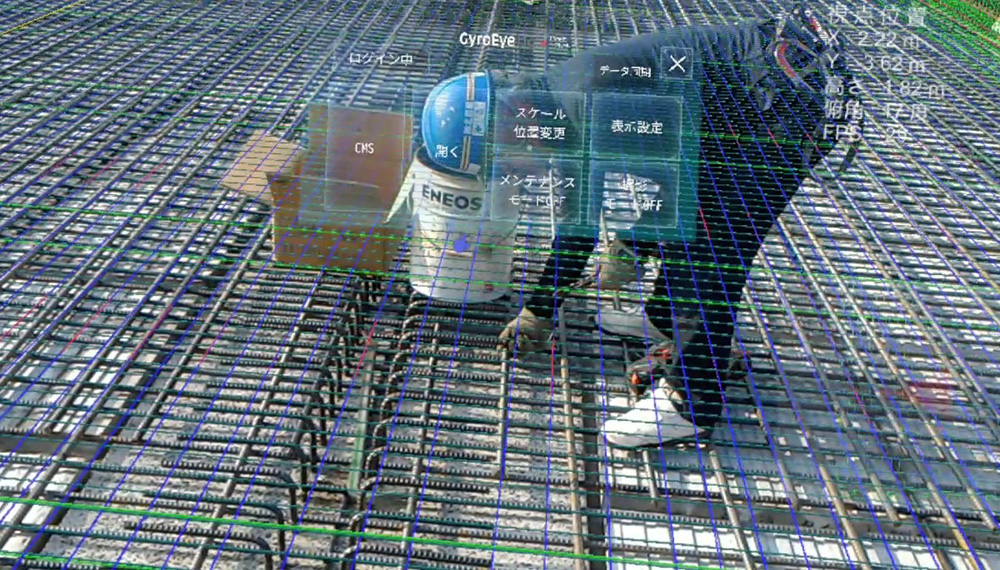
The sunglass-like equipment is HoloLens developed for utilizing the augmented reality (AR) technology at construction sites. The equipment has a built-in microscopic monitor on each glass-like section. The craftsman was positioning the reinforcing bars so as to overlap the actual reinforcing bar with the BIM model projected on the monitor.
The software named GyroEye Holo, developed by Informatix Incorporated, was used for converting the BIM model data for reinforcing bars and others into images that may be viewed through HoloLens.
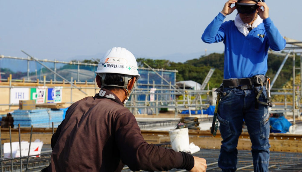
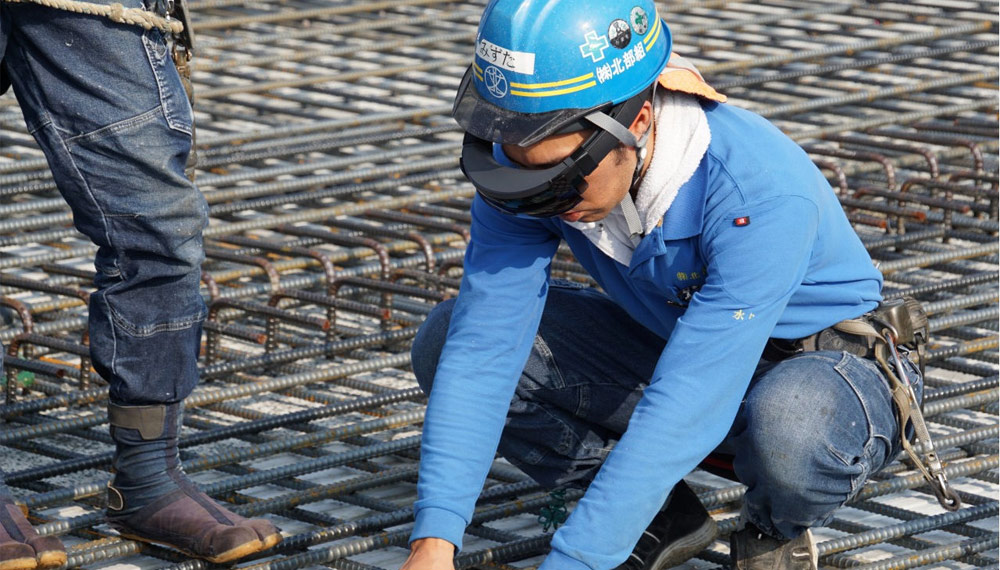
“We have tried to arrange reinforcing bars without marking them in ink by inputting the bridge BIM model data prepared for the construction work into HoloLens. In a near future, such an AR device might come to be used naturally at all construction sites,” commented a construction worker at the site with a smile.
In the conventional reinforcing bar arrangement work, the position of a reinforcing bar was calculated using drawings and measuring tape and marked on a concrete mold with a magic marker. These intermediate steps are not necessary when the AR device is used. The work would be finished with significantly improved speed because reinforcing bars need only to be aligned with the BIM model at the site.
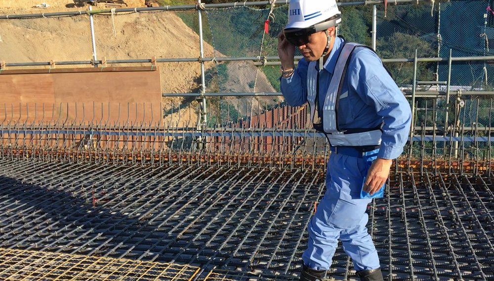
After casting concrete, anchors that support drainage facilities and inspection platforms are driven. With the AR device, reinforcing bars embedded in concrete may be viewed through without relying on drawings or a hammering test. Therefore, anchors may be installed promptly without worrying about damaging the reinforcing bars inside.
The finished shape inspection on reinforcing bars conducted by the project owner is also likely to change significantly. Reinforcing bars may be checked at a glance as to whether they have been arranged as designed, just by comparing the reinforcing bars at the site with the BIM model through the AR device. Therefore, the owner may even conduct 100% inspection on the arranged reinforcing bars by himself.
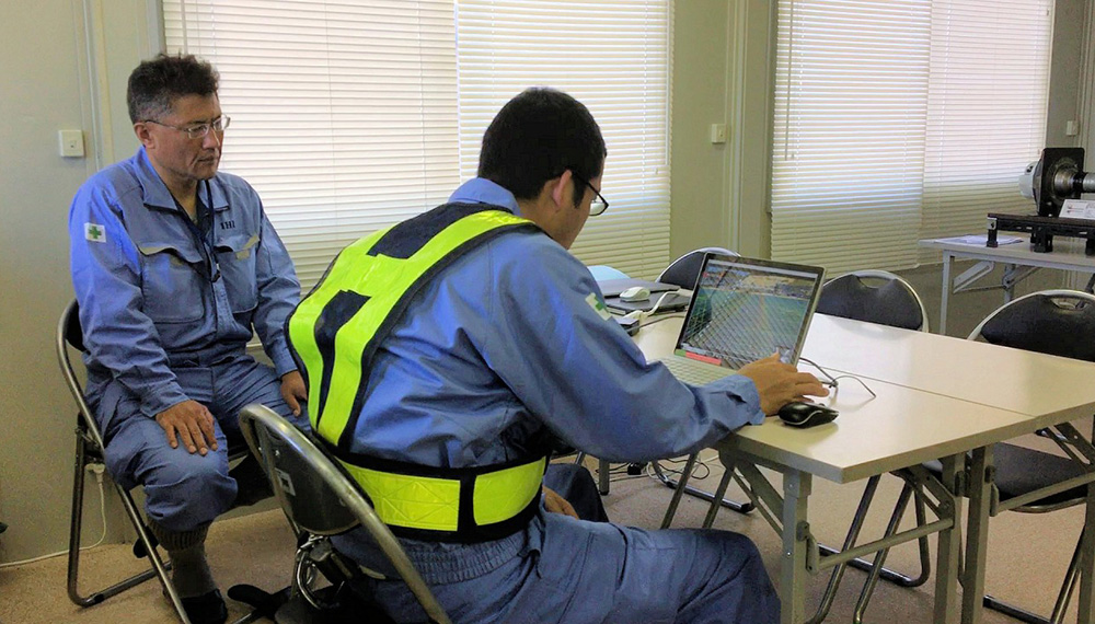
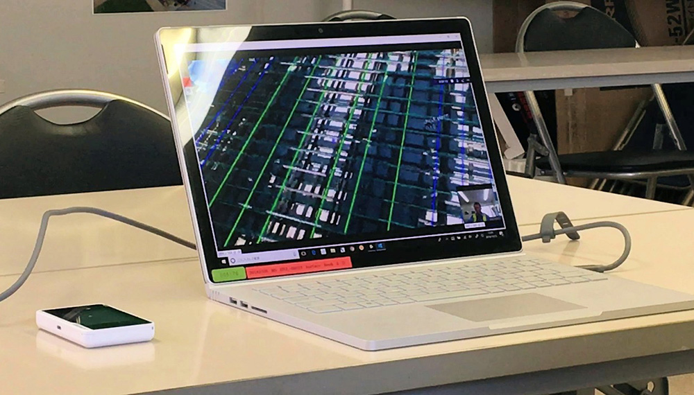
“At the construction site, a test was performed to relay the images seen through the AR device on a real-time basis to the construction office via the Internet, to have them viewed by the supervisor on the owner side. In the future, it might even become possible to relay these images to the office of the project owner,” says Leader Koji Konno of Sales Division of Informatix Inc. that developed GyroEye Holo.
That being possible, the supervisor may inspect on the finished shape from a remote location, even from his office. A supervisor who is in charge of numerous construction sites may curtail the amount of time needed for traveling and spend more time for inspection. This would lead to enhancement of productivity and sophistication of quality assurance processes for the owner also.
Virtual construction planning using BIM model
Reinforcing bar arrangement and finished shape management became possible through the AR device only because of the BIM model that faithfully reproduces the members constituting the bridge. Their forms and dimensions were configured in the computer and a simulation was performed on the form of the completed bridge and the construction processes before starting the actual work at the site.
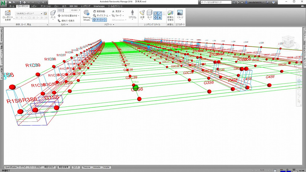
The people of Office K1 Co., Ltd. that participated in the consortium were in charge of the BIM model creation. The 3D model was configured based on the 2D drawings of the bridge using a tool named Click3D developed by the company, to complete the BIM model that may be handled by the 3D CAD software AutoCad.
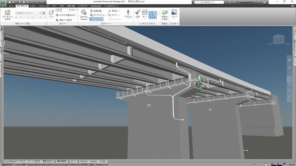
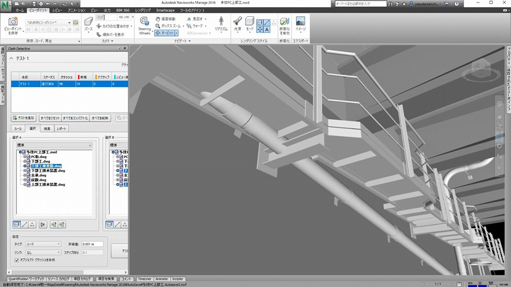
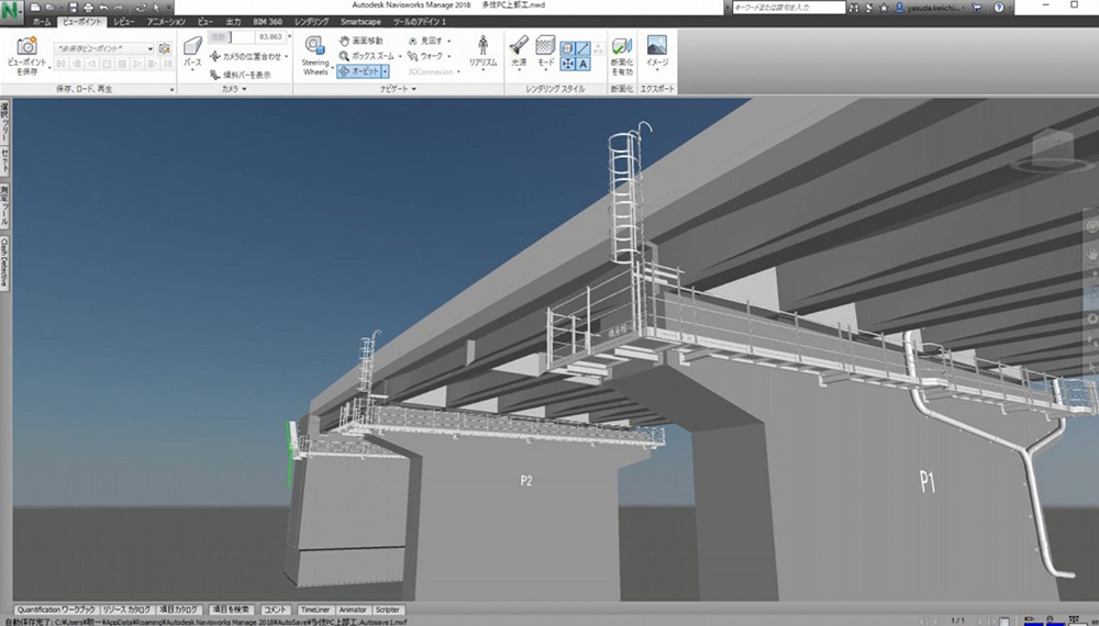
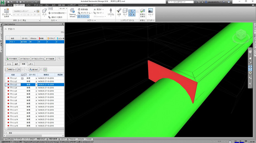
The data of drainage facilities, inspection platforms, ladders and other accessories were input into the model in the 3D format, and interfering sections where members interfere with each other were searched out and corrected using the 3D model integration software Navisworks. Thus, the finished form without any interfering section was completed on the computer.
Representative Director Keiichi Yasuda of Office K1 Co., Ltd. commented that, “We became aware that construction workers and craftsmen have numerous needs unique to them for the first time after working with them at the site. It provided a good opportunity for us because we had spent most of our time in the office when preparing 3D models.”
The topographic form was created using the software named Infraworks for the BIM model, and 3D parts, such as the bridge and cranes used in the construction work, were loaded. Then, construction planning was conducted based on the 4D model that links the 3D model with the construction schedule by simulating the movements of cranes and frame girders and the situations of each type of construction work. Furthermore, visual representation of the finished shape of the structure was made.
The video was also used at meetings with managers of partner companies, as well as at confirmation meetings for work processes held before starting each of them, which proved to be useful for sharing information on construction processes and safety measures.

Real-time management of the fresh concrete thickness and the timing of concrete casting at a joint with hardened concrete
In the construction work, efforts were made to enhance the productivity of construction management and upgraded quality control by linking the BIM model data with surveying equipment. One of such efforts was for the real-time management of floor slab concrete casting.
Reinforcing bars are arranged closely in two tiers in the vertical direction in floor slabs. Concrete needs to be compacted carefully so that no void can be formed. Also, concrete needs to be cast at joints with the concrete that has already hardened, for all the portions of the floor slab within a set time period. This is for avoiding formation of discontinuous surfaces called a “cold joint.”
An automatic tracking-type total station was installed at the top of a hill overlooking the entire bridge surface, for casting high-quality concrete within the limited time period. The floor slab for a span was divided into 15 blocks, and the height and position of fresh concrete floor slab and the time were automatically measured and recorded.

While the concrete was being cast, the results of management work were sent to the tablets possessed by construction management engineers for real-time management of the work progress for each section of the floor slab and the timing of concrete casting on joints.
The system named Concrete Navi developed by Chiyoda Sokki Co., Ltd. was used for the purpose.
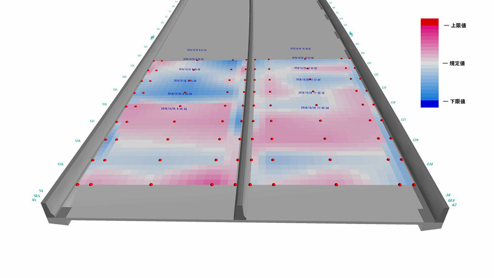
The finish was instructed so that the cast surface height would satisfy the required design quality, while comparing the finished surface of the BIM model with the actual cast surfaces, throughout the casting work until it was completed.
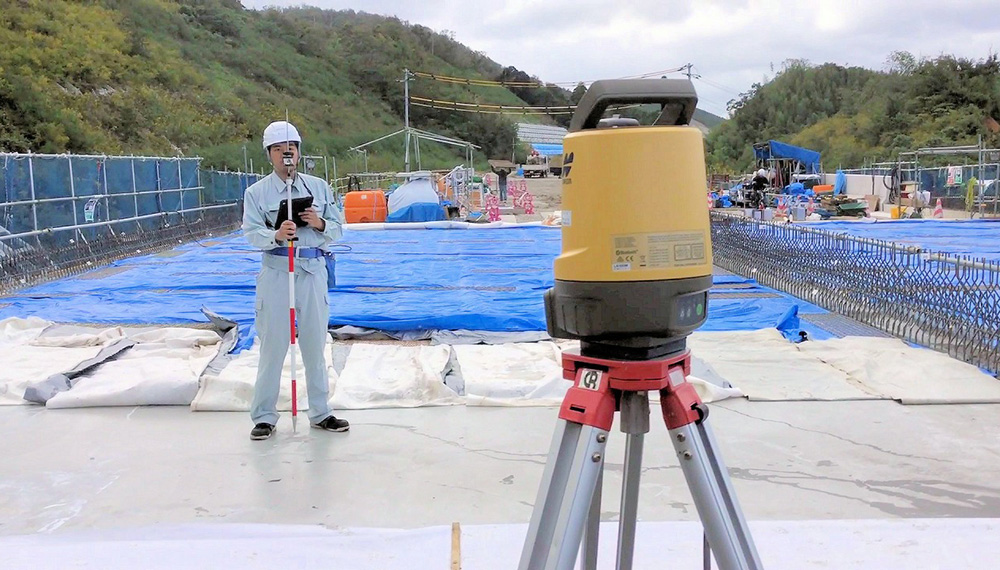
In the finished shape inspection conducted for confirming that the shape and dimensions of the floor slab are as designed after completion of concrete casting, measurements were taken using the software BIM360 for tablets that utilizes the coordinates data of the BIM model and the surveying equipment named LN-100 that enables surveying work to be done by one person.
Ink marking was also conducted by one person by a similar method, on the concrete molds for balustrades and the medial divider formed on the floor slab.
The survey results were compiled for color-coding and displaying the differences from the design values on a 3D model using the software named Finished Shape Contour developed by Office K1 Co., Ltd., so that confirmation would be possible at a glance that the entire bridge surface has been finished within the allowable values.
Deputy General Manager Yukio Hirahara of Solutions Sales Division of Chiyoda Sokki Co., Ltd., who proposed the system, explained that, “When casting concrete on bridge girders, cambers for raising the girders beforehand and deflection that occurs during casting also need to be considered. Many attempts were made for linking the BIM model with the surveying equipment properly, so that the height and thickness of the concrete floor slab may be managed at a glance on a real-time basis.”
The BIM model at the time of completion is passed down for maintenance and management
The BIM model used in the construction work is delivered to the project owner, after inputting the data on the shape and attributes at the time of completion using CIM-PDF developed by Office K1 Co., Ltd., and with various types of construction work records and slips stringed. The BIM model will be utilized when the structure is put to service and also for its maintenance and management.
The project was selected as one of the projects for introducing and utilizing innovative technologies aimed at dramatically enhancing the productivity at construction sites, to be executed by the Ministry of Land, Infrastructure, Transport and Tourism by utilizing the Public/Private R&D Investment Strategic Expansion Program (PRISM) framework of the Cabinet Office.
IHI Construction Service Co., Ltd. in charge of the construction work organized a consortium with three other companies namely IHI Corporation, Office K1 Co., Ltd. and Chiyoda Sokki Co., Ltd., and achieved dramatic enhancement of productivity and sophistication of quality management at the same time. The construction site has indeed been a place of open innovation where companies from different areas of profession collaborated for promoting technological innovation.
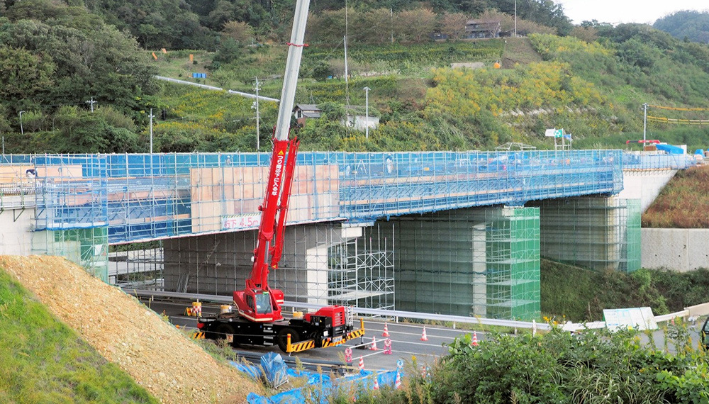
“The project was for a three-span PC bridge measuring 76 m in length, which is of a standard scale in our country. Many bridges of a similar scale is being built at various places. The results obtained in the project by linking the BIM, AR and surveying equipment are likely to prove useful in construction work for other bridges also,” commented General Manager Sadaaki Nakamura of Development Division of IHI Construction Service Co., Ltd., while reflecting on the project.